(Hong Kong)


Product Summary
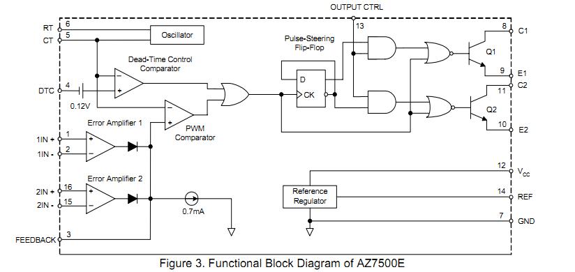
The AZ7500EP-E1 is a voltage mode pulse width modulation switching regulator control circuit designed primarily for power supply control. The AZ7500EP-E1 consists of a reference voltage circuit, two error amplifiers, an on-chip adjustable oscillator, a dead-time control (DTC) comparator, a pulse-steering control flip-flop, and an output control circuit. The applications of the AZ7500EP-E1 inlcude SMPS, Back Light Inverter and Charger.
Parametrics
AZ7500EP-E1 absolute maximum ratings: (1)Supply Voltage, VCC: 40 V; (2)Amplifier Input Voltage, VI: -0.3 to VCC + 0.3 V; (3)Collector Output Voltage, VO: 40 V; (4)Collector Output Current, IO: 250 mA; (5)Package Thermal Impedance, RθJA: 73℃/W; (6)Lead Temperature 1.6mm from case for 10 seconds: 260℃; (7)Storage Temperature Range, TSTG: -65 to 150℃; (8)ESD rating: 200 V.
Features
AZ7500EP-E1 features: 1)Stable 4.95V Reference Voltage Trimmed to ±1.0% Accuracy; (2)Uncommitted Output TR for 200mA Sink or Source Current; (3)Single-End or Push-Pull Operation Selected by Output Control; (4)Internal Circuitry Prohibits Double Pulse at Either Output; (5)Complete PWM Control Circuit with Variable Duty Cycle ; (6)On-Chip Oscillator With Master or Slave Operation.
Diagrams
 |
 AZ7500B |
Other |
|
Data Sheet |
Negotiable |
|
||||
|
AZ7500C |
Other |
|
Data Sheet |
Negotiable |
|
||||
|
AZ755 |
Other |
|
Data Sheet |
Negotiable |
|
||||